Blender create a picture frame with shear and bevel
In this tutorial for Blender in english we will see how to make the frame of a picture with two interesting tools, Shear and Bevel. Shear generally allows to deform an object only along a certain axis at a time, using handles that can be dragged, and can be useful both for modeling and for animation; the Bevel function is usually used to smooth the edges of the mesh without using modifiers such as the Subdivision Surface, although in our case we will use its own particular property that allows you to customize the shape of this bevel.
Building the frame with the Shear tool:
We start Blender, we position ourselves in top view by pressing the 7 key of the numeric keypad and we do not delete the default cube, but we move it to the left by 8 units (it does not matter if you are working in meters or in centimeters we are just creating a generic example), by pressing the "G" key and then "X", writing -8 and pressing ENTER.

(The cube is much thicker than a frame, but we will need it to emphasize the grooves that will be created)
We select the X-Ray view at the top

and in Edit Mode we move the top face of the cube up, by pressing the "G" "Y" keys, writing the value 14 and confirming by pressing ENTER

We select the Shear tool on the left

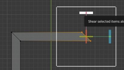
and a system with two handles will appear around the vertices we selected. We drag down the handle on the right

The popup window of the properties of the Shear tool has appeared at the bottom left showing "Offset", ie the length of the path through which the handle was dragged, the two axes that will correspond to the movements imposed by the tool, the reference for the orientation and the possibility of using the Proportional Editing or not

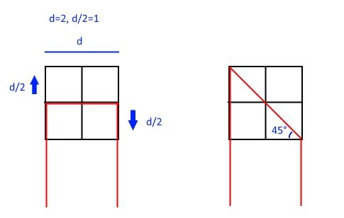
If we consider our cube d = 2 units wide, to rotate its face 45 degrees we will have to phase it out by a distance equal to d / 2 = 1 unit

therefore in the popup window we will assign to Offset a value equal to -1 (i.e. downwards in the relative system of handles)

and we will get the rotation of 45 degrees

we extrude 16 units to the right, by pressing the "E" "X" keys, writing 16 and confirming with the ENTER key. This time we will use the handle at the top to rotate the face

drag it and the popup window will appear at the bottom left. Since we have to rotate the plane 90 degrees, we will need an Offset of 2 units, so we write -2

(the plus or minus sign of the offset depends on the direction in which we are moving the handle)
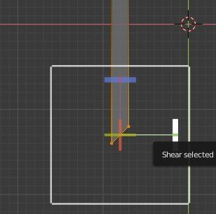
We extrude downwards, by pressing the "E" "Y" keys by writing -28 and confirming by pressing the ENTER key. Now drag the handle on the right to rotate the face of the cube

We write -2 as the Offset value and we get

Now select the left part of our frame and move it down, pressing the "G" "Y" keys, writing -12 and confirming with the ENTER key, thus obtaining

We activate the Shear tool and use the right handle, writing Offset value:1 and we get

We select the two faces at the ends and press the "X" > "Only Faces" key to delete them

Here we press the CTRL + E keys and select "Bridge Edge Loops" to join them

obtaining

Create the grooves with the Bevel function:
We uncheck the X-Ray option at the top right

we activate the "Edge select" selection mode at the top left

with a double click of the left mouse button we select the upper internal edges

pressing CTRL + B, we activate the Bevel function and by dragging the mouse we define the area of influence

In the popup window at the bottom left, containing the parameters of the Bevel function, we set the value of the number of segments to 5, to begin defining the most important points of the grooves

(as you can see on the right the numbers of loops selected in the frame have also increased)
Now activate the "Custom Profile" option and drag the points to define the shape of the profile of the frame we want to obtain

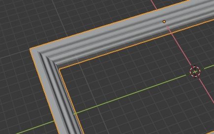
All the changes made on the curve have created an interesting result on the frame, but we see that the grooves are not well defined, they are too square, compared to the soft curves that we had created

So let's increase the number of Segments to 25

Thus obtaining a more interesting result

To obtain a more realistic frame we could scale it, halving its height, by pressing the "S" "Z" keys, writing 0.5 and confirming by pressing the ENTER key.

Here ends this tutorial on how to make frames with the Shear and Bevel tools, a method that also allows you to create interesting moldings to be used both in furniture and as decorations on the corners of the internal walls of houses. Happy blending!
