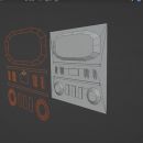
How to add a reference image in Blender
In this tutorial we will see how to add and insert a reference image in Blender (version 4.1+). The images used as references can be useful, in every phase of creating a 3D scene, both to be able to draw inspiration from them, and to check if we are creating a work that is similar to reality, and to trace the various views of an object when it is particularly complex or the artist is still a beginner.
To import a reference image into Blender there are many ways, such as using the "Images as plane" add-on or creating a window, where you can then select an "Image Editor" to load our image, but the most natural way to load it is undoubtedly using the "Background" and "Reference" objects.
These two objects are actually a single object with different settings, an "Empty" object that also displays the associated image in "3D View", while in rendering it behaves like an "Empty" object, so it is invisible. In fact, these two objects, even if presented differently and distinct from the "Empty" object, are nothing more than the "Empty" object itself with the "Display As" option set as "Image" (which you can, alternatively, add from the menu with "Add > Empty > Image")
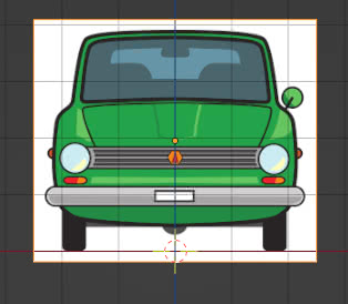
In the first examples we will show the "Reference" object and as a reference image we will use the one downloaded from Pixabay https://pixabay.com/vectors/car-green-vintage-automobile-auto-4234031/ , which we have divided into the "Front", "Side", "Top", "Back" views so that they were less cumbersome in the 3D View. Alternatively, you can always use the same image, including all the views, duplicating it, rotating it, moving it so that the image of the correct side of the car is positioned appropriately, so that it corresponds well to the desired view.
Let's now show this object and what its options are, and then show a practical example, building a reference system that could be useful, eventually, to create a car model.
"Reference" and "Background" object options:
To load a reference image in the 3D View, press the "Shift+A" keys (or use the "Add" menu) and choose "Image > Reference"
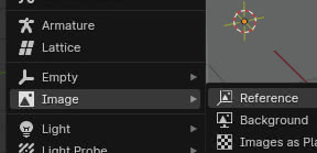
The "Blender File View" will automatically open, allowing us to navigate the directories to search for and load the image we want to use as a reference. As you can see on the right, in the file browser, there is only one option "Align To View"
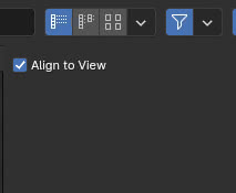
if it is activated, this will force the image to be loaded so that it is orthogonal to the user's view, chosen before creating the object.

If the "Align To View" option is not activated, the image will be loaded and placed "lying down" on the X and Y axes, as if we had added any plane with an image inside
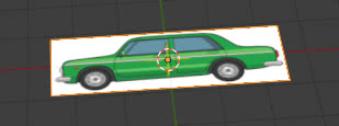
If we look at the "Outliner", we notice (as we have already announced) that it is an "Empty" object, with the image we have loaded associated with it (in our case "side.jpg")
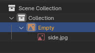
Like every "Empty" object, it has its own customized "Object Data Properties" tab
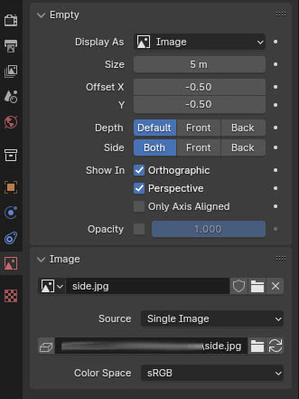
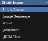
in whose "Image" panel, we can notice that the "Source" option suggests the possibility of loading, as a reference, in addition to single images, also sequences of images, movies, images generated internally by Blender (those needed for mapping), or UDIM files
Alternatively, we can also import an image by dragging it into Blender, starting from a file browser. All the settings previously set (such as "Align To View") or the default ones will be maintained.
Let's now examine the various options of the "Reference" object:
Size:
The "Reference" object can be moved, rotated, resized using the usual Blender commands, but it also has additional tools that can help its practical use. In fact, if we position the mouse on its associated image (5 meters wide when loaded, as we saw in the options panel), we will notice that some lateral handles and an "X" appear.
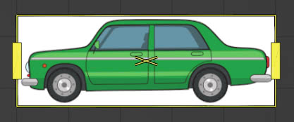
If we drag the handles, the image will be resized, keeping the proportions intact, while if we place the mouse on the "X" and hold down the left button, we can drag the image, regardless of the Blender tool selected to the left of the "3D View".
As if we were in a customized "Edit Mode", resizing performed with this method will not affect the size scale; in fact, if we look at the panel on the right (the one that can be called up by pressing the "N" key), we notice that in the "Item" tab the value of "Scale" has remained unchanged
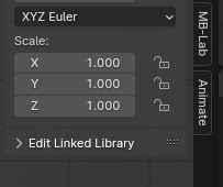
while the value of "Size" has changed (which has gone, in our case, from 5 to more than 7 meters)

while if we resize the image with the usual modifier tools, the value of "Scale" will change, while the value of "Size" will remain unchanged.
(If you have the "Object Data Properties" tab open, when you resize the image it may happen that the value of "Size" does not change immediately. To update it, just position the mouse on its value field.)
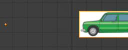
Offset X and Y: these two measures express the horizontal and vertical deviation from the origin. However, their values are not expressed in the current unit of measurement, but as a percentage: the default values (-0.5, -0.5) indicate that the image is shifted by (-50%, -50%) from the origin, that is, it is centered in it.
Setting "Offset X" equal to zero, the origin is now on the left side, allowing the image to be rotated around the left side,
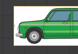
while if we set "Offset X:1" the image will not be shifted by one to the right, but by 100%, that is, equal to the value of "Size" which is, in our case, 5 meters.
Opacity: by activating this option, by checking the relative box, we can adjust the transparency of the reference image, setting 0 if we want the image completely transparent, 1 if completely opaque. Let's now see its use by talking about the other options.
Depth: indicates how the reference image should be seen in relation to the object we want to model.
If we set "Default" the visibility depends on the relative position: the images that are behind the objects are seen behind, the images that are in front are seen in front. At first glance it may not seem useful, but if we have to change the positioning of the image often, it may be more practical to act only in the "3D View", without going to the properties continuously to change the settings.
"Front" and "Back" depend on the situations and our habits/preferences. In fact, if we are in this situation
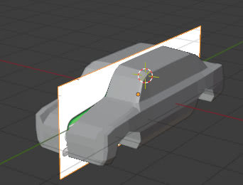
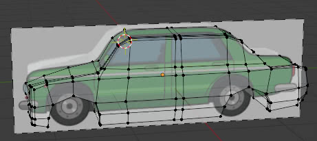
where we are modeling half of a car, using the "Mirror" modifier to automatically generate the other half, if we choose the "Front" option the image is positioned in front of the car model (and in front of the other objects present)
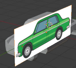
we can then decrease the opacity value of the image, for example 0.4, so that it can be seen through the profile of the model and model the car in "Edit Mode" also using the "Display Mode: Solid".
If instead we choose the "Back" option, the image is seen behind the car model (and behind the other objects present)
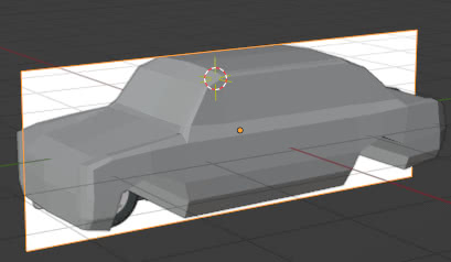
in this case we can also use a completely opaque reference image ("Opacity:1") however, since the object now completely covers the reference, to model in "Edit Mode" we will have to activate the "X-Ray" option, adjusting its intensity (for example with a value of about 0.5) in the "Viewport Shading" menu at the top right
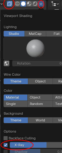
so we can, in this case too, work easily

Side: Indicates on which side the image is visible. "Both" indicates that it is visible on both faces. "Front" means that the image is only visible on the front side (the one facing up if the image is laid out), this is especially useful when we want to create a reference image system, where the front image of a car should not be visible in the back view, or when we have placed a series of reference images, but we do not want them to be visible yet when we are modeling and we are rotating the view in the "3D View". "Back" means that the image is only visible on the back side (being able to switch from "Front" to "Back" can be useful when we do not want to rotate or move the "Empty" object)
Show In:
"Orthographic": When we build a reference image system, we place the reference images in the front, side, top etc. views which are usually seen in orthographic mode. So we activate this option for them.
However, we can continue to see them "obliquely" if, looking at the 3D View from any angle, we press the "5" key on the numeric keypad to switch to this type of view

"Perspective": by activating this option, the images are also shown in perspective view; it is also useful for reference images that we use as inspiration, for example during sculpting.
"Only Axis Aligned": if we activate the "Orthographic" and also "Perspective" options we increase the possibilities of viewing in multiple modes, by checking the "Only Axis Aligned" box, instead, we limit the display to the axes only, that is, we see the images only when the view is along the axes (for example the front view, along the Y axis, the side view, along the X axis, the view from above, along the Z axis) both in orthographic and perspective mode.
"Background" or "Reference" object?
As we said before, the "Background" and "Reference" objects are more or less the same and differ in the values of "Depth" and "Side":
Background: Depth = Back, Side = Front
Reference: Depth = Default, Side = Both
This is because, as we can see from the example image

The "Background" objects (1) are more suitable to provide a basis on which to build the model, while the "Reference" ones (2)(3) are more suitable as sources of inspiration or temporary references (and even in this case you can see what the "Align To View" option is for, to load the images in the current view for what we need at the moment).
(The images for the "Reference" objects were also downloaded from pixabay.com)
Let's create a system of reference images to model:
Now let's load a set of reference images, positioning them according to some views, which will allow us to have all the information necessary to create the object we want to model. We will also use a parallelepiped that will help us to correctly place the images.
(We will use the images of the various views of the car shown previously)
Let's press the "1" key on the numeric keypad, to go to the orthogonal front view, and add a "Background" object (press the "Shift+A" keys and choose "Image > Background") to load the "front.jpg" image, with the "Align To View" option activated, so it will be loaded orthogonally to the front view.
We center the image of the car and position the wheels so that they are "on the X axis" (this operation could also be done after having built the entire model, but it is useful to have more information on the relative positioning of the images)
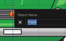
We press the "F2" key and rename the image with "Front"
In the "Outliner" window we click on the "funnel" shaped button and activate the selectability option
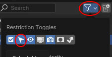
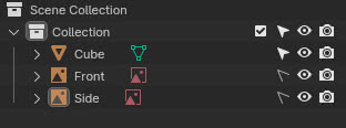
then we deactivate it for the "Front" object

We add a cube, pressing the "Shift+A" keys, choosing "Mesh > Cube", press the "Shift+Z" keys to switch to "Wireframe" view with "X-Ray" enabled. Then by moving and resizing it in "Object Mode" and moving the vertices in "Edit Mode" we adapt it to the dimensions of the car body, matching the edges to half of the black outline of the drawing.

Back in "Object Mode", after pressing the "Tab" key, we press the "3" key on the numeric keypad to switch to the side view, then we add another "Background" object by loading the image "side.jpg".
Move and enlarge the image, so that it coincides more or less with the height of the cube; if the drawing is not precise, try to make an average between the height of the body, the distance of the wheels from the Y axis etc. Then modify the cube, making it a parallelepiped, deforming it only along the Y axis, to adapt it to the length of the car.

We change the name of the "Background" object to "Side" and uncheck the editability.
From now on, the parallelepiped will no longer have to be modified (even if we have not unchecked it); in fact, we have set all three of its dimensions: width and height with the front image, length with the side image.
Now press the "7" key on the numeric keypad and notice that the parallelepiped is oriented "vertically"
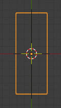
When we add the new "Background" object, loading the "top.jpg" image, we will therefore have to rotate it (-90 degrees), move it and resize it, always looking for average values in case the drawing is imprecise.
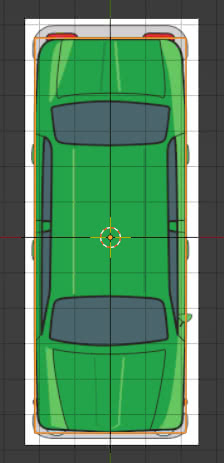
Once we have done this, we give the object the name "Top" and inhibit its modification, unchecking "selectable", as we did with the other objects.
Finally, we press the "CTRL" key and "1" key on the numeric keypad, to access the back view: we see the profile of the selected parallelepiped and also the profile of the front view image, which is invisible because the "Side:Front" option is active (so it does not interfere with the modeling work of the back of the car)

If the "Side:Both" option had been chosen, which shows the image on both sides, we would have seen instead
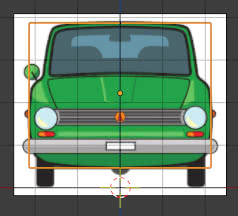
which could create problems in the references of the back view.
With the same procedure as the other times, we add a "Background" object (loading the "back.jpg" image) and position/resize the image, using the parallelepiped as a reference
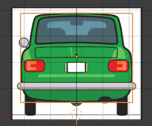
Once this is done, we deactivate the editability.
We have thus created our system of reference images; in perspective view we will not see anything, except our parallelepiped, because we have not activated the relative option

in this way, however, we will be able to see at what point the modeling of our object is, without having the clutter of the reference images.
To make them reappear, simply return to orthographic view by pressing the "5" button on the numeric keypad

(We see the images apparently positioned in a disorderly way, also due to the "Depth:Back" option, but the important thing is that they perform their function in the various orthogonal views)
Looking in the "Outliner" we see a list of reference images, that cannot be modified, with our parallelepiped

we can eliminate the latter, considering that the reference images have all been positioned and we can, if necessary, group these in their own non-modifiable "References" collection, so that we can also hide them and make them reappear more quickly, leaving the main collection free to place the object that we need to model

For this tutorial on how to importing reference images is all. Happy modeling and blending!
