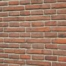
Blender: bricks with adaptive subdivision/microdisplacement
In this third tutorial for Blender (updated to version 2.93) concerning the creation of a 3D wall starting from a photo ("Blender course: from photo to 3D wall"), we will see how to create the bricks of the wall using the Adaptive Subdivision, which is also called Adaptive Displacement, or Micropolygon displacement, or Microdisplacement, or Tesselation, so many names is because in Blender this functionality does not correspond to a single command, as in the case of the "Displace Modifier", but to a set of settings to be made (therefore it has not been assigned an official name), both because in the technical literature some functions have been called in different ways, and because this method has not one but two interesting characteristics: adaptivity and micropolygons.
Adaptive Subdivision/Displacement:
In the previous tutorial https://www.graphicsandprogramming.net/eng/tutorial/blender/modeling/blender-bricks-displace-modifier we created a brick wall with the "Displace" modifier, which used uniformly an equal number of vertices/polygons to create the bricks throughout the wall, but in a more complex case, with a wall longer, we might be interested in seeing more clearly, with more detail, the closest blocks, while bricks further away can also be made with fewer vertices, as they are further away and less visible. This function is realized through the Adaptive Subdivision: as you can see in the figure
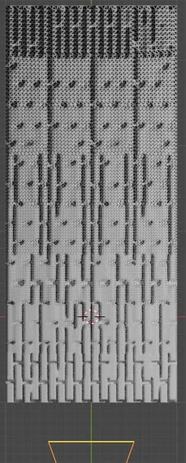
the part of the wall closest to the Camera, at the bottom, uses more vertices to represent the closest objects, while the farther ones are made up of fewer vertices, with suitable reflections and shadows that subside at a lower resolution.
Micropolygons:
Another fundamental feature of the Microdisplacement are the micropolygons, which allow you to add details to a mesh, only during the rendering phase, starting from an image. From this point of view the maps used are somewhat reminiscent of bump maps, which added small details sensitive to light using the material, only in this case in the rendering the mesh will really look deformed, as if we were using a "Displace" modifier. In Blender we can also choose the size of the micropolygons (from 0.5 px upwards) obviously the larger they are, the coarser the resulting perturbation of the mesh will be.
Creating bricks with the Microdisplacement:
Let's use an example similar to that of the previous tutorial, concerning the "Displace" modifier: let's create a centered plane, importing the "diffuse_map.jpg" image depicting the wall, calling the addon with "File > Import > Images as Planes"
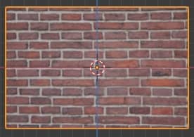
We then import the lamp from the example of the previous tutorial, or press the "Shift+A" keys and then choose "Light > Sun", create a "Sun" lamp with Strength:4.5 with position (X:-2.88183 m, Y:-1.41398 m, Z: 2.8909 m) and rotation (X: 48.7941°, Y: -1.17007°, Z: 297.408°).
We then create a Camera, leaving the default values and with position (X:1.17253 m, Y:-2.66012 m, Z:-0.016343 m) and rotation (X:90°, Y:0°, Z:22.2°).
Let's now proceed with the construction of the bricks of the wall, in 4 steps:
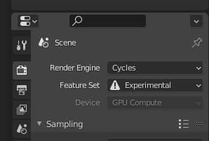
1. For years the Microdisplacement has been classified among the "experimental features" and works only with the Cycles rendering engine, so in the "Render Properties" tab of the "Properties Window" we set "Render Engine:Cycles" and "Feature Set:Experimental"
2. Select the plane in "Object Mode", click on "Shading" at the top to access the materials workspace, where the nodes are present, press the "Shift+A" keys and we add with "Texture > Image Texture" the map of displacement "displacement_map.jpg". Always pressing the "Shift+A" keys we create the "Vector > Displacement" node, which regulates the intensity of the overhang, which we place between the texture and the "displacement" port of the "Material Output"
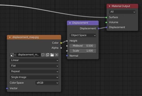
In this way we connected the map from which to read the data for displacement.
To better control the displacement results, let's unlink the "diffuse" texture from the "Principled" shader for now.
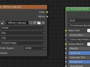
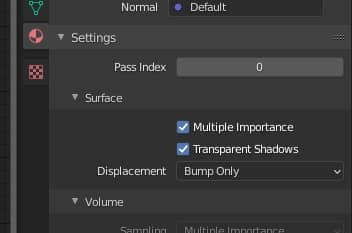
3. In the previous step we linked the displacement map to the "Material Output", but its "displacement" port was used only by the "bump map" to simulate small details on the surface; now we want to change its functionality, so we go to the "Material Properties" tab and in "Settings > Surface > Displacement" we change the option from "Bump Only" to "Displacement Only" (only "Displacement" because we want to use this function only for displacement)
4. We select the plan and associate a "Subdivision Surface" modifier to it, which is used to adjust the subdivision rate of the micropolygons, in which we check the "Adaptive Subdivision" option to activate the subdivision that changes according to the distance from the Camera (and "Simple" to keep the edges of the plane unchanged).
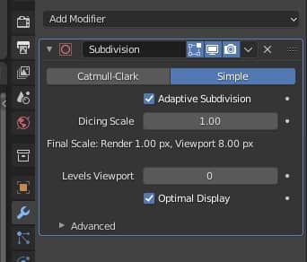
The "Dicing Scale" parameter allows you to change the definition scale of the microdisplacement both for the "Rendered" preview in the 3D Viewport and for the actual Rendering (in order to work easily on other parts of the scene, saving computational resources). For instance

by default the values 1px for the "Render" and 8px for the "Viewport" are set, which are the dimensions of the micro-polygons we talked about before, so in "Render" smaller micropolygons will be used, while in "Viewport" more large, thus easing the calculations during the preview.
These default values can be changed in the "Render properties" tab in the "Subdivision" sub-panel,
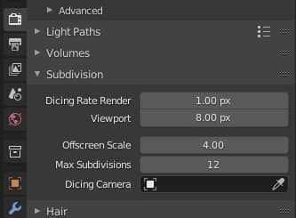
where, eventually, you can set smaller values for the "Render", but not less than 0.5, or give "Viewport" larger values if you have resource problems.
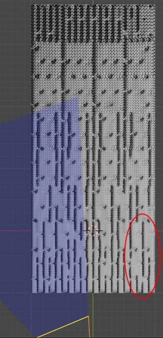
In the sub-panel "Subdivision" we see three other parameters, such as "Offscreen Scale" which specifies what must be the definition of the parts of a mesh that are out of the Camera view. For high values of "Offscreen Scale" the parts out of sight will be represented saving on resources, for example by rotating the Camera and setting the Offscreeen Scale value to 25, there is a saving in the circled parts furthest from the view,
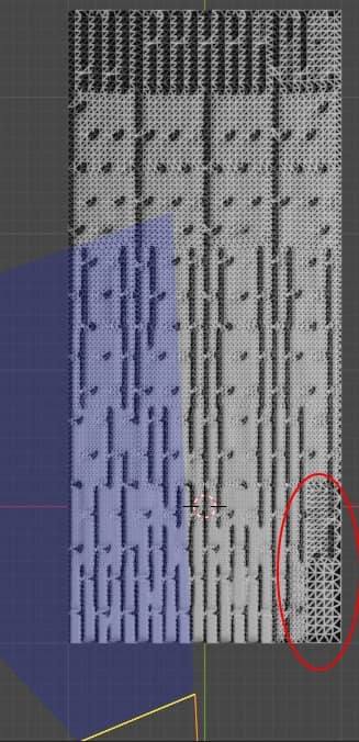
while for low values, for example 1, the parts most hidden from the camera view are more defined.
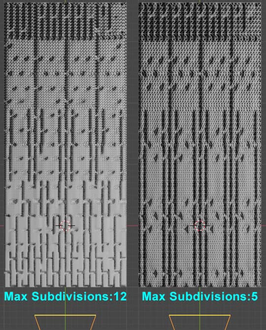
The "Max Subdivisions" parameter, on the other hand, establishes a ceiling on the definition of the mesh: even if for a certain distance more divisions can be carried out than the entered parameter, it does not perform any. In fact, if we compare the situation with the default value 12 with a value of 5 for "Max Subdivisions", we notice that even if we get closer to the Camera the number of subdivisions does not increase, but at a certain point it stops.
In the last parameter "Dicing Camera" we can also insert a reference Camera for the calculation of the subdivisions, so that no artifacts are created during the animations.
Returning to the realization of our wall, as in the tutorial concerning the "Displace" modifier we insert, as "Environment texture" in the "World Properties", the image hdr "neurathen_rock_castle_2k.hdr"
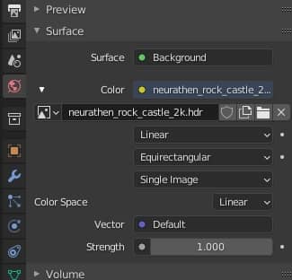
Since our scene is simple and with few vertices, in order to be able to observe our object more easily we also give a size of micropolygons equal to 1px in the viewport

We enter the "Rendered" view mode and we notice that the bricks are too protruding
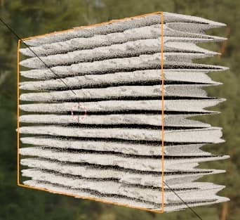
We then go to the "Shading" workspace and in the "Displacement" node we decrease the value of "Scale" bringing it to 0.015

obtaining a result more corresponding to our wishes
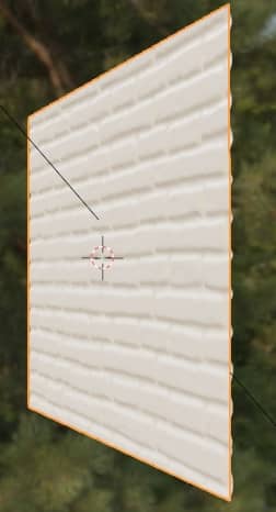
By pressing the 3 key on the numeric keypad in the viewport, we look at the side wall and we notice that the bricks are in relief but moved "inside" the mesh, while we want them to protrude outside.

then we change the value of "Midlevel" (in our case we set it to zero)
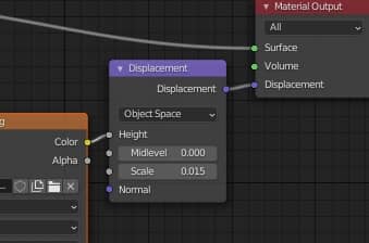
to bring the bricks to level.

From the Camera view (obtained by pressing the 0 key on the numeric keypad) we can already see an interesting brick wall.
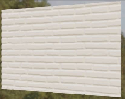
Now let's reconnect the texture of the "diffuse map", let's change the value of "Specular" to 0.177
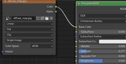
and we get
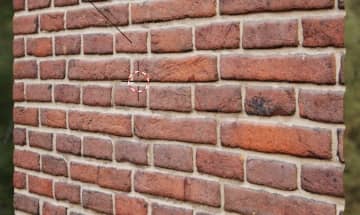
Obtaining, as in the case of the "Displace" modifier, a good shape for the bricks of the wall.
The adaptive subdivision leads to benefits as it allows you to save on memory, allowing you to render faster and create more complex scenes with the same hardware resources, optimizing vertices with the distance from the Camera, with a mesh that will remain light in the modeling phase, postponing the details to the rendering phase. On the other hand, it still has some flaws:
- Can be used with the Cycles render engine, but not with Eevee.
- By displaying the reliefs only in the rendering, the microdisplacement cannot be used for objects intended for 3D printing (a plane with an associated Adaptive Displacement, in Solid view only one plane remains, without the reliefs added with this method, and so on will result in any other software where it will be exported)
- In the modifier stack, the adaptive "Subdivision Surface" to work well must be at the bottom, in order to be the last modifier used before rendering; if it is moved first it will lose some of its properties: let's consider as an example a "sequence of asteroids"

made from this object (a cube to which a previously non-adaptive "Subdivision Surface" modifier had already been applied)

with the experimental version of Cycles set, material with "Surface> Displacement: Displacement Only" option and material with a "Noise Texture" texture with "Displacement" node
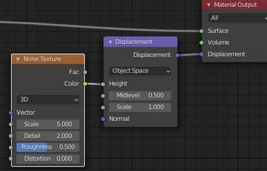
and adaptive "Subdivision Surface" modifier after an "Array" modifier
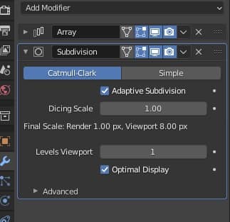
the result will be what you want

while if we drag the "Subdivision Surface" modifier on top of the "Array" modifier, making it act like this before, it will "magically" transform into a non-adaptive modifier, losing all its properties stated above
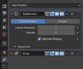
One last remark: if you create instances, remember to place the camera in front of the original object.
We save the file as "adaptive_subdivision_microdisplacement.blend".
You can download the project files here:
displacement_map.jpg
diffuse_map.jpg
adaptive_subdivision_microdisplacement.blend
world hdri
That's all for this adaptive subdivision tutorial; we have seen that it is a very useful tool, even if at times it has limitations and unwanted behaviors. We hope that in the future it will be improved and become a standard for Blender as well.
See you at the next tutorial, where we will see how to give our wall a PBR (Physically Based Rendering) material in order to make it as realistic as possible. Happy Blending!
Back to "Blender course: from photo to 3D wall" course

